2026 Best Types of Pipe Valves for Industrial Use
Industrial piping rarely operates under ideal conditions. A valve may face hot condensate, abrasive slurry, frequent cycling, or pressure changes within one shift. Choosing the wrong design can restrict flow, increase maintenance, or create avoidable downtime. Details matter. A small chemical line and a high-capacity cooling-water header do not have the same needs.
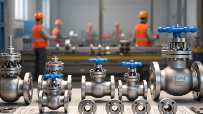
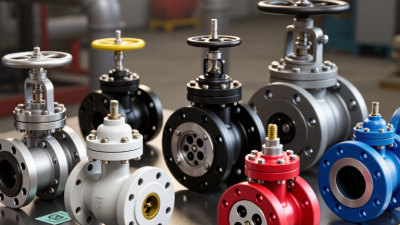
This guide to the best types of pipe valves for industrial use in 2026 introduces common designs and their practical roles. Gate valves are often used for straightforward isolation, while globe valves allow more controlled flow adjustment. Ball and butterfly valves can provide quick shutoff, though their suitability depends on the service and installation. Check valves help limit reverse flow. Diaphragm valves may suit certain corrosive or contamination-sensitive processes. None is best everywhere.
Selection should start with the actual operating conditions. Check the fluid, temperature, pressure, pipe size, connection type, and required flow behavior. Then review material compatibility and the manufacturer’s published pressure and temperature limits. A stainless-steel body, for example, does not automatically make every wetted component suitable for a chemical service. That detail is easy to miss.
This overview is a starting point, not a substitute for engineering review. Product names and ratings can vary between manufacturers, and site conditions are sometimes less tidy than a specification sheet suggests. Compare verified documentation, maintenance access, and operating demands before choosing pipe valves. The right choice is specific.
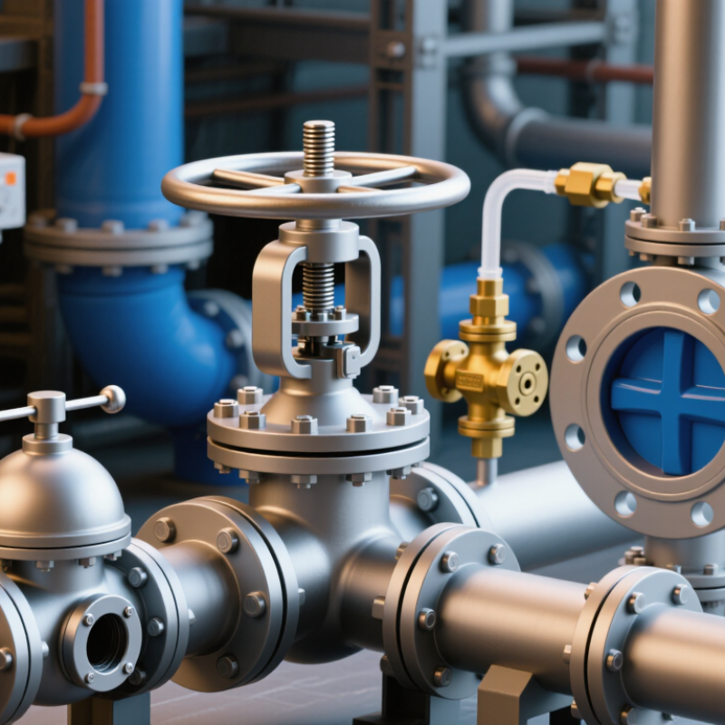
Define Industrial Pipe Valves and Their Flow-Control Functions
Industrial pipe valves are mechanical devices installed in pipelines to start, stop, direct, or regulate fluid flow. They also help prevent reverse flow and protect equipment from excessive pressure. Different jobs. Gate and ball valves generally provide tight shutoff; globe and control valves are better suited to adjusting flow. Check valves close when flow reverses, while relief valves open at a set pressure. The right choice depends on the fluid, operating temperature, pressure, and how often the valve moves.
Flow control affects energy use, not just throughput. The U.S. Department of Energy’s Improving Steam System Performance: A Sourcebook for Industry reports that steam systems account for about 30% of energy use in U.S. manufacturing. Its Improving Pumping System Performance sourcebook notes that pumping systems can consume 25–50% of energy in some industrial plant operations. These figures make valve selection worth careful review: a poorly sized control valve can create needless pressure loss, while a valve used mainly for isolation may not need precise throttling. In the field, deposits, vibration, and changing process demands complicate tidy design calculations. Engineers should verify actual operating conditions and maintenance access, rather than rely on pipe size alone.
Compare Gate, Globe, Ball, Butterfly, Check, and Plug Valve Designs
Industrial pipe valves serve different duties, and their internal shapes affect flow, pressure loss, and maintenance. Gate valves suit lines that stay fully open or closed; their wedge moves slowly and creates little obstruction when raised. They are poor choices for frequent throttling. Globe valves offer finer flow control, but the curved path adds pressure loss. That trade-off matters.
Ball valves open with a quarter turn and provide tight shutoff in many services. Their fast action is useful, though sudden closure can create pressure surges. Butterfly valves also turn quickly, with a compact disc that suits large-diameter lines. They save space, but the disc remains in the flow path. Check valves need no operator to prevent reverse flow. Their closure depends on flow conditions, so poor sizing may cause chatter or water hammer. Small details count.
Plug valves use a rotating, bored plug to start, stop, or divert flow. They can handle some dirty services, but buildup may make operation harder. Compare all six designs against the fluid, temperature, pressure, line size, and required shutoff. A valve name alone is not enough. I would also check access for maintenance; that step is easy to overlook when a line drawing looks tidy. Verify material compatibility and operating limits against project requirements before selection.
How to read this chart: Scores are general design-fit ratings on a 1–5 scale, not measured performance data. Higher scores indicate a stronger typical fit for that attribute. Actual performance depends on valve design, size, materials, and operating conditions. Check valves prevent reverse flow and are not substitutes for isolation valves.
Match Valve Types to Pressure, Temperature, and Process Conditions
For industrial service, select a valve against the full operating envelope, not just the line’s normal pressure. ASME B16.34 provides pressure-temperature ratings by material and class; check the rating at the actual metal temperature. A valve rated for high pressure at room temperature may have a lower allowable pressure near a hot process limit. Leave room for startup surges and thermal cycling. The details matter.
Valve function and fluid behavior matter just as much. Gate valves suit isolation, while globe valves offer more controlled throttling and can create greater pressure drop. Ball and butterfly valves provide quick shutoff, but solids, viscosity, and erosion can affect sealing and service life. For corrosive or contaminated fluids, verify body, trim, seat, and seal compatibility together. One weak material choice can set the maintenance schedule.
The U.S. Department of Energy’s Improving Steam System Performance: A Sourcebook for Industry reports that steam accounts for about 30% of energy used in manufacturing. That makes steam-line valve selection consequential: confirm pressure-temperature ratings, condensate behavior, and safe isolation requirements. For abrasive slurry, inspect wear paths and ask how easily the valve can be serviced. A neat specification can still miss real operating swings; reviewing plant logs with operators is often useful.
Apply ASME B16.34 Pressure-Temperature Ratings from Class 150 to 2500
Industrial valve selection starts with the pressure and temperature conditions the valve must actually withstand.
ASME B16.34 provides pressure-temperature ratings across Classes 150 through 2500, with allowable ratings tied to material groups and operating temperature. A class number is not a pressure value in psi. Nor does Class 600 have the same allowable pressure at every temperature. Check the applicable rating table for the valve material and design temperature.
That distinction matters.
A steam line operating hot may have a lower allowable pressure than the same material at ambient conditions. Include foreseeable pressure surges, too, rather than sizing only for steady operation.
Gate, globe, ball, and check valves serve different flow and shutoff needs, but the pressure class alone does not determine suitability. Confirm that the selected valve’s construction, ends, and materials match the piping specification and service conditions. For a high-pressure process line, a Class 1500 valve may be appropriate, but only if its temperature-adjusted rating covers the design case.
Small details count.
In real projects, temperature data can be incomplete or change during operation; that uncertainty deserves review, not a convenient assumption. Have qualified engineering personnel verify the selection against the current standard edition and project requirements before procurement.
Verify Valve Testing and Leakage Limits Under API 598 or ISO 5208
For industrial pipe valves, a pressure test is only useful when its limits match the purchase specification. API 598 and ISO 5208 define inspection and pressure-testing requirements, but their acceptance criteria are not interchangeable. The required procedure depends on valve type, size, pressure class, and the standard edition named in the contract. Check those details before testing begins.
Record shell and seat test pressures, hold times, test medium, and observed leakage. Keep the valve clean and dry enough to spot a slow drip at the seat or body joint. Small details matter. A calibrated gauge and a stable test setup help make results repeatable. ISO 5208 includes leakage-rate designations; API 598 sets acceptance requirements for covered tests. Confirm the exact allowable leakage against the applicable table and specification, rather than assuming every valve must show zero leakage. That assumption can cause disputes.
A tidy report can still leave questions. Was the test performed in the specified direction? Were cavity pressure and temperature considered? These checks deserve attention, especially for resilient-seated and metal-seated designs. Neither standard proves a valve will perform perfectly in every operating condition; installation, wear, and fluid properties also matter. Keep the test record with the valve’s identification and inspection documents.