What Are the Top Types of Hose Fittings in 2026?
Hose fittings connect flexible hose to pumps, tools, vehicles, and fixed equipment, yet they are easy to underestimate. The right connection helps control leaks, movement, and pressure loss. The wrong one may loosen under vibration or fail to match the hose’s inner diameter. Small details matter.
In 2026, common options include threaded fittings, barbed fittings, crimp fittings, quick-connect couplings, push-to-connect fittings, and flanged connections. Each suits different installation needs. A quick-connect coupling can speed up tool changes, while a crimp fitting creates a firm, permanent connection when matched to the hose and crimp specifications. Thread type, material, pressure rating, temperature range, and conveyed fluid all affect compatibility. A brass fitting may work well in one setting, while stainless steel or another approved material is more appropriate in another. There is no universal “best” fitting.
This guide compares the leading hose fittings by design, typical uses, advantages, and limitations. It also highlights practical checks, such as confirming hose size, inspecting seals, and following the fitting manufacturer’s installation instructions. Ratings should be verified for the complete hose assembly, not assumed from a fitting alone. Even experienced buyers can miss a mismatch when dimensions look nearly identical. That deserves a second look. The aim is to help readers make a careful, application-specific choice rather than select a fitting based on appearance or price alone.
Hose Fitting Basics: Connection Types, Pressure Ratings, and SAE J517 Hose Compatibility
Hose fittings do more than connect a hose to a port; they determine the sealing method, installation needs, and service limits. Common types include JIC 37-degree flare, ORFS, tapered NPT, BSP, and flange connections. They are not interchangeable. Similar thread diameters can hide different pitches or sealing faces, so confirm thread and seat details before assembly. A thread gauge and careful inspection are more reliable than appearance alone.
Pressure ratings usually refer to working pressure, not burst pressure. Check the rating for the complete assembly, including hose, fitting, and any adapters; the lowest-rated component sets the limit. Account for pressure surges, temperature, and repeated flexing, too. SAE J517 specifies requirements for hydraulic hose types, but it does not make every hose compatible with every fitting. Match the hose family, inside diameter, reinforcement, and fitting series, then follow the specified crimp dimensions. One detail is easy to miss: a hose may fit a fitting physically but still fail the required assembly specification. A visual check cannot confirm compatibility.
Threaded and Flared Fittings: 37° Connections in SAE J514 and ISO 8434-2
For hose assemblies carrying hydraulic fluid, 37° flared fittings remain a practical choice when metal-to-metal sealing and service access matter. SAE J514 and ISO 8434-2 specify 37° connections; the angle is a measurable design feature, not a guarantee of interchangeability. Their thread forms, dimensions, and mating details still need checking. The standards are the primary technical references for selecting compatible fittings.
The flare’s conical face makes the seal, while the nut supplies clamping force. Keep both surfaces clean. A scratch, burr, or misaligned tube can create a leak under pressure. In the field, inspect the flare for even contact before tightening, then use the applicable assembly torque rather than guessing by feel. Small detail. Big consequence. Hose and fluid-power industry reports track reliability and maintenance as major operating concerns, but those broad findings do not replace fitting-specific validation. A 37° connection can be robust, yet it is not foolproof; I would still question any installation that relies on thread engagement alone. Check SAE J514 and ISO 8434-2 against the fitting and tube specifications before assembly.
What Are the Top Types of Hose Fittings in 2026?
Threaded and Flared Fittings: 37° Connections in SAE J514 and ISO 8434-2
Both SAE J514 and ISO 8434-2 specify a 37° flare connection. The matching flare angle alone does not guarantee that fittings are interchangeable; verify thread form, size, and applicable standard requirements.
Crimped Hose Ends: Design and Performance Requirements in SAE J516
Crimped hose ends join a hose to a threaded or otherwise connected fitting through a compressed metal sleeve. The crimp must grip the hose without cutting its reinforcement or restricting its bore. SAE J516 sets requirements for covered hydraulic hose fittings, including design dimensions and performance criteria. The applicable details depend on fitting style and the standard’s current revision.
Compatibility is critical. A fitting, hose, and crimp specification should be treated as a matched assembly, not interchangeable parts. During production, technicians use the specified dies and crimp diameter, then check the finished sleeve with suitable measuring tools. A fitting that looks neat can still be under-crimped or over-crimped. Small differences matter. Relevant qualification testing may assess leakage, pressure capability, or impulse performance, depending on the assembly and requirements.
Inspection should include the fitting, hose insertion depth, and crimp appearance. Look for uneven compression, damaged reinforcement, or a sleeve that has shifted. Keep records of hose and fitting specifications, crimp measurements, and test results; these help trace problems later. Field conditions can be less tidy than a test bench, and visual checks alone cannot confirm performance. That limitation deserves attention. Verify the exact SAE J516 revision and follow the assembly maker’s documented instructions before putting a crimped assembly into service.
Quick-Disconnect Couplings: ISO 7241 Interchange Types A and B
Quick-disconnect couplings can save time when hydraulic lines need regular removal. Under ISO 7241, Types A and B are two common interchange designs. Their profiles and dimensions differ, so a Type A plug should not be assumed to fit a Type B socket. Match the coupling type, size, and pressure rating before installation.
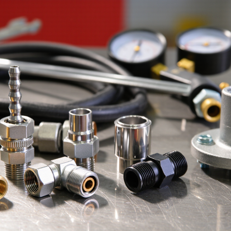
On a workbench, the details are easy to spot: the plug enters the socket, and a locking sleeve secures the connection. Internal valves help limit fluid loss when the coupling separates, though a few drops can remain on the faces. Keep those faces clean. Grit trapped near a valve can cause leakage or make a sleeve stick. That matters.
ISO interchangeability does not make every coupling suitable for every system. Check the applicable ISO 7241 series, working pressure, fluid compatibility, temperature range, and flow requirements. Relieve line pressure before disconnecting unless the coupling is specifically rated for connection under pressure. A practical check is to compare the marked type and size with the equipment documentation, then test for leaks at operating conditions. I would not rely on appearance alone; similar-looking fittings can have different dimensions or performance limits.
Flat-Face Couplings and Selection: ISO 16028 Standards and Pressure-Temperature Ratings
Flat-face couplings suit circuits where clean connection matters. Their flush mating surfaces limit fluid loss during disconnection and reduce dirt traps. ISO 16028 defines interface dimensions and performance requirements for this coupling type; it does not assign one pressure rating to every size or material. Check the coupling’s own pressure-temperature table. Ratings vary with seal compound, body material, size, and test conditions. Small details matter.
Treat pressure and temperature as linked limits, not separate boxes. A coupling rated for a given pressure at room temperature may need derating when hot. Cold starts can also stiffen seals and make connection harder. ISO 4413 requires hydraulic systems to account for component limits and operating conditions, so the weakest rated part constrains the circuit. Compare maximum working pressure, impulse duty, fluid compatibility, and temperature range against real operating peaks—not just the normal gauge reading. Confirm the mating halves follow ISO 16028, then inspect seal condition and connection cleanliness during maintenance. Standards help, but they do not replace application testing. And field conditions can be messy.